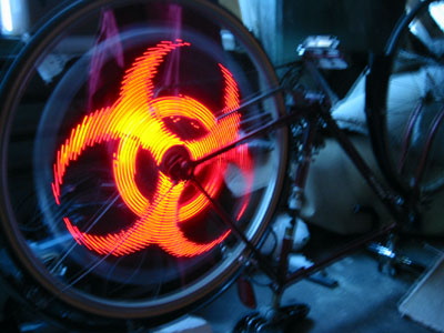
 ඔන්න කාලෙකට පස්සේ ඉලෙක්ට්රොනික ලිපියක් දාන්න යන්නේ.....මේකෙන් පුලුඒන් අපේ පුට් සයිකලේ වීල් එක ලස්සන කරගන්න.....ලස්සන කරගන්න කිව්වේ ලස්සන එල්.ඊඩී බල්බ් සෙල්ලමක් දාන්න...ඔන්න යටින් වැඩේ ගොඩ දාගන්න හැටි තියනවා......හරියට කරගන්න එකයි තියෙන්නේ............
Tools
- For fabricating the PC boards:
- Computer and laser printer
- Hacksaw
- Stainless steel wool
- Pulsar toner transfer papers and green TRF film
- Clothing iron
- Ferric chloride
- Liquid tin solution
- Long tupperware containers
- Plastic funnel
- Dremel with drill press attachment
- 0.04" carbide drill bit
- For soldering components:
- Soldering station
- Solder sucker
- Multimeter
- Bench power supply
- Needlenose pliers
- Diagonal cutters
- For programming the microcontrollers:
- PIC programmer with In Circuit Serial Programming (ICSP) capability
- Computer
- For mounting the boards in a bike wheel:
- Utility knife
- Ruler
- Fine tipped marker
- Safety gear:
- Safety glasses
- Nitrile rubber gloves
- Leather gloves
- Earplugs
- Dust mask
Parts list
| Qty. | DigiKey part No. | Description |
| 3 | PIC16F628A-I/P-ND | PIC 16F628A microcontroller |
| 3 | A9418-ND | 18 pin IC sockets |
| 12 | 296-1600-5-ND | 74HC595 eight bit shift register |
| 12 | A9416-ND | 16 pin IC sockets |
| 100 | 2N3904FS-ND | 2N3904 transistors |
| 200 | 160-1620-ND | Red oval LEDs |
| 100 | 1.0KEBK-ND | 1K 0.125 watt resistors |
| 200 | 180QBK-ND | 180 ohm 0.25 watt resistors |
| 3 | 10KQBK-ND | 10K 0.25 watt resistors |
| 3 | P5174-ND | 1uf 16 volt electrolytic capacitors |
| 3 | 399-2171-ND | 0.1uf ceramic capacitors |
| 6 | DN6851-A-ND | Hall effect sensors |
| 3 | 497-1441-5-ND | 7805 voltage regulators |
| 1 | 182-1018-ND | Double sided 0.032" 1/2oz copper clad board |
| 1 | PC300C-60-ND | 0.04" carbide drill bit |
| 1 | 182-1003-ND | Pulsar toner transfer sheets |
| 1 | 182-1021-ND | Pulsar green TRF film |
- Only 3 hall effect sensors are required but one of mine was faulty, so I’ve specified 6 in the table.
- The carbide drill bit is very hard, but also very brittle. Make sure you don’t apply any lateral loads.
- I’ve specified 0.032" copper clad board which is half the thickness of the regular stuff. This is so that it will fit through the "Toner Applicator" from Pulsar. If you don’t plan to use this device, then you can use thicker board.
Printed circuit board
In the past, I’ve used the photo etch method to make circuit boards, but the process was difficult, costly, messy and time consuming. This time, I decided to try the toner transfer method. This is a process whereby you use a laser printer to print your PC board layout on a special sheet of paper, then you transfer the toner from the paper to the copper clad board with heat and pressure. After the toner has been "re-fused", the paper is removed by soaking the board in water. Finally, a sealant is applied over top of the transfered toner to prevent pinholes when the board is etched.The three boards for the Spoke POV were done in this way. I used toner transfer sheets from Pulsar, and applied them to the copper clad boards with a common household iron (no steam). Although I was successful in making three functional boards, I found the process finicky and one board needed a lot of touch up work to make it serviceable. Most of my troubles came from trying to transfer the PC layout from the paper to the copper clad board - It was hard to get it to stick evenly without smearing or shifting. Pulsar caims that their "Toner Applicator" product makes this process more reliable, so I may order one and give it a try. If anyone would like to share their experiences with this, please contact me.
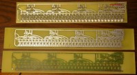
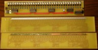
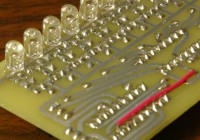
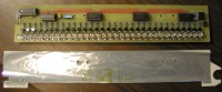
Board photos:
The following images show the boards in three different stages of completion:- Bottom - immediately after etching and drilling, before the toner and green TRF film (sealer) has been scrubbed off.
- Middle - after scrubbing and tinning.
- Top - the finished board with all components soldered in.
Parts placement:

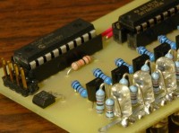
Soldering the LEDs:
It gets a little crowded once you start soldering the LEDs and current limiting resistors. You may want to consider soldering all the resistors first, then the component side LEDs and finally the solder side LEDs.Wheel mounting
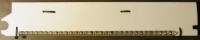
The sintra backing:
To mount these boards in the wheel, I made a protective backing out of 1/8" sintra (often used as a rigid backing onto which printed material can be mounted), covered one side with anti-static plastic that was cut from a motherboard bag and attached it to the solder side of the circuit boards with zip ties. I’m not sure if the anti-static plastic is of any benefit, but I used it as a precaution in case a static charge builds up on the sintra as the wheel spins.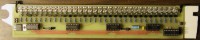
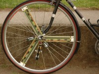
Attaching them to the wheel:
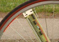
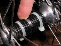
On one end of the sintra, I cut a crescent shaped notch that matched the radius of my front hub shaft. On the other end, I cut a notch for the spoke nipple. All that is needed to secure a circuit board to the wheel is two zip ties at the spoke nipple end - the other end stays put because the crescent shaped notch engages around the wheel hub. To keep the hub end of the boards in place, I used two short sections of plastic hose, slit down one side, wrapped around the hub shaft and attached with zip ties. These act as spacers that prevent the boards from sliding laterally along the length of the hub shaft.Note: These boards will only fit a 700c or larger wheel. They are too long for 26" mountain bike wheels. Also, when using three boards, it’s easier to mount them in a wheel with a number of spokes that’s divisible by three (IE 36 spokes).
Mounting the batteries
The batteries are mounted in between the circuit boards, affixed to intersecting pairs of spokes with zip ties. Initially I was going to use lithium polymer or lithium ion batteries for this project, but that meant buying an expensive charger in addition to expensive cells so I decided to just go with AA nickel metal hydride batteries instead. The circuit runs nicely on 7.2 - 7.4 volts, so that means six nickel metal hydride or two lithium cells can be used.Although I was able to run this device with only six AA batteries, I ran into trouble whenever I tried to display an image that turned on almost all the LEDs simultaneously. Because the boards will draw almost six amps with every LED on, I found that the voltage would drop to a point where the microcontroller would no longer operate. I’ve been able to confirm the source of the problem because it runs fine if I disconnect two of the boards. To address this problem, I’m going to use 12 AA batteries (six parallel pairs) with heavier gauge wire connecting them. The photo of the completed wheel above shows six batteries in their normal place plus and extra six in a seperate holder that were added to address the voltage drop problem.
0 comments ගණන:
Post a Comment